
JS Wheel
- ASCOM interface
- 7 slots
- USB powered
A filter wheel is a quite simple object: a carousel of filters, electronics and motor to move it, a case that contains them and connect the camera the wheel and the telescope.
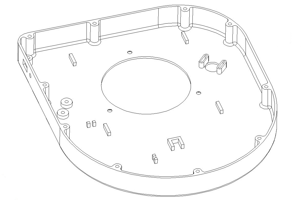
To minimize the manufacturing complexity I’ve decided to realize the wheel and the upper and lover cases using a 3D printing service; a little bit expensive but extremely cheap compared to CNC machining.
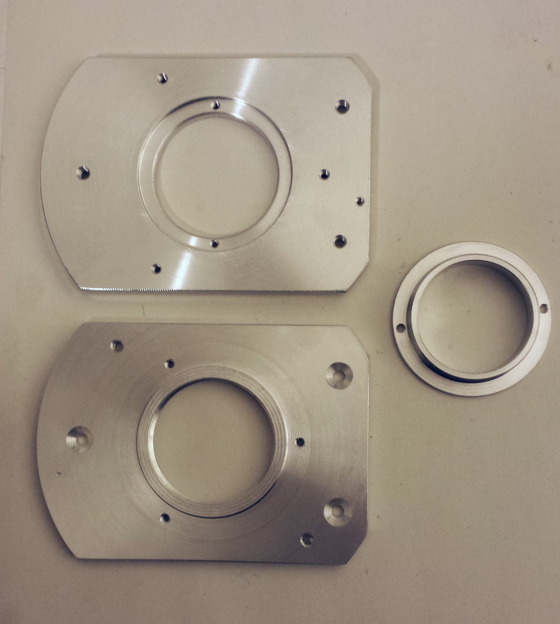
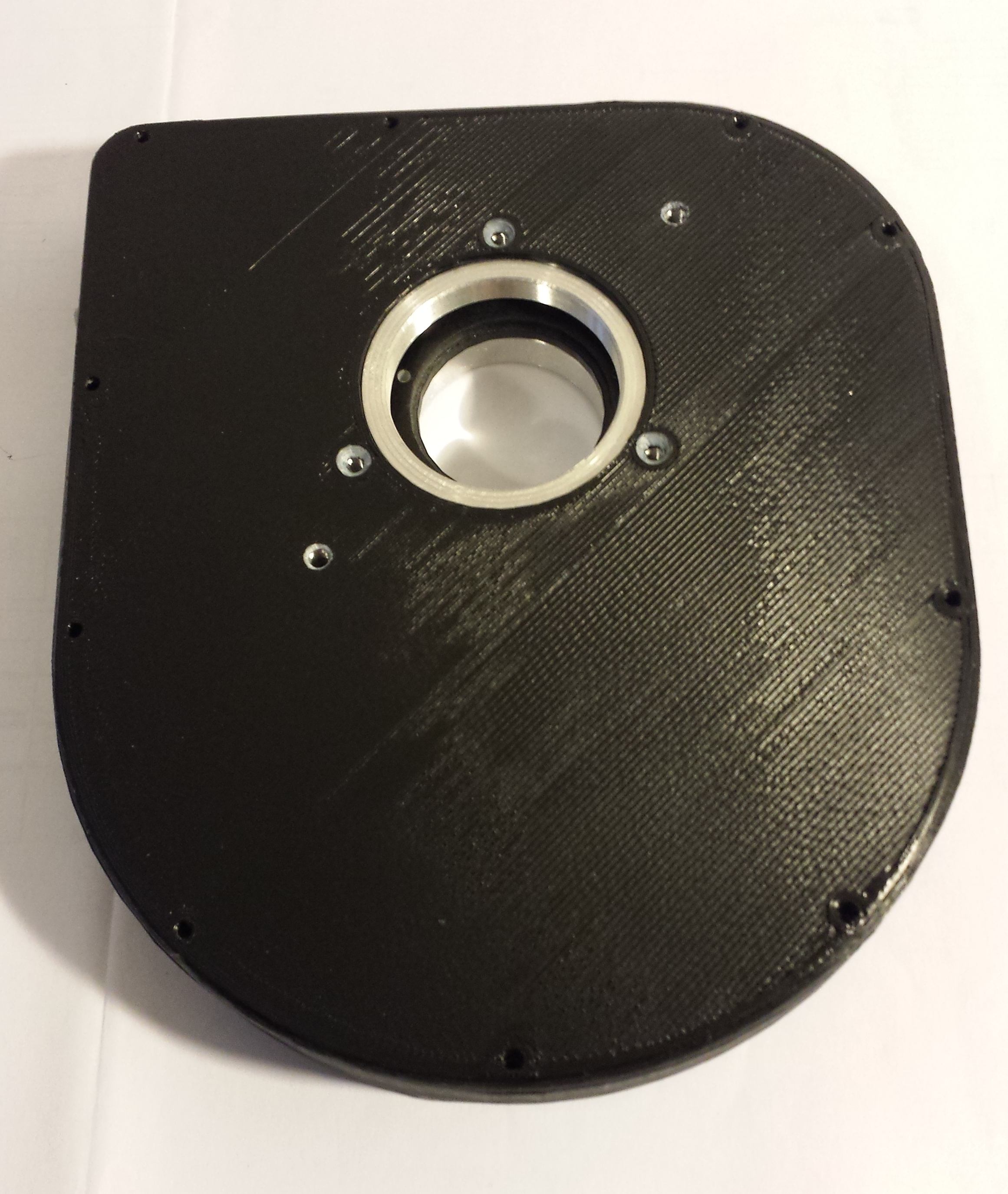
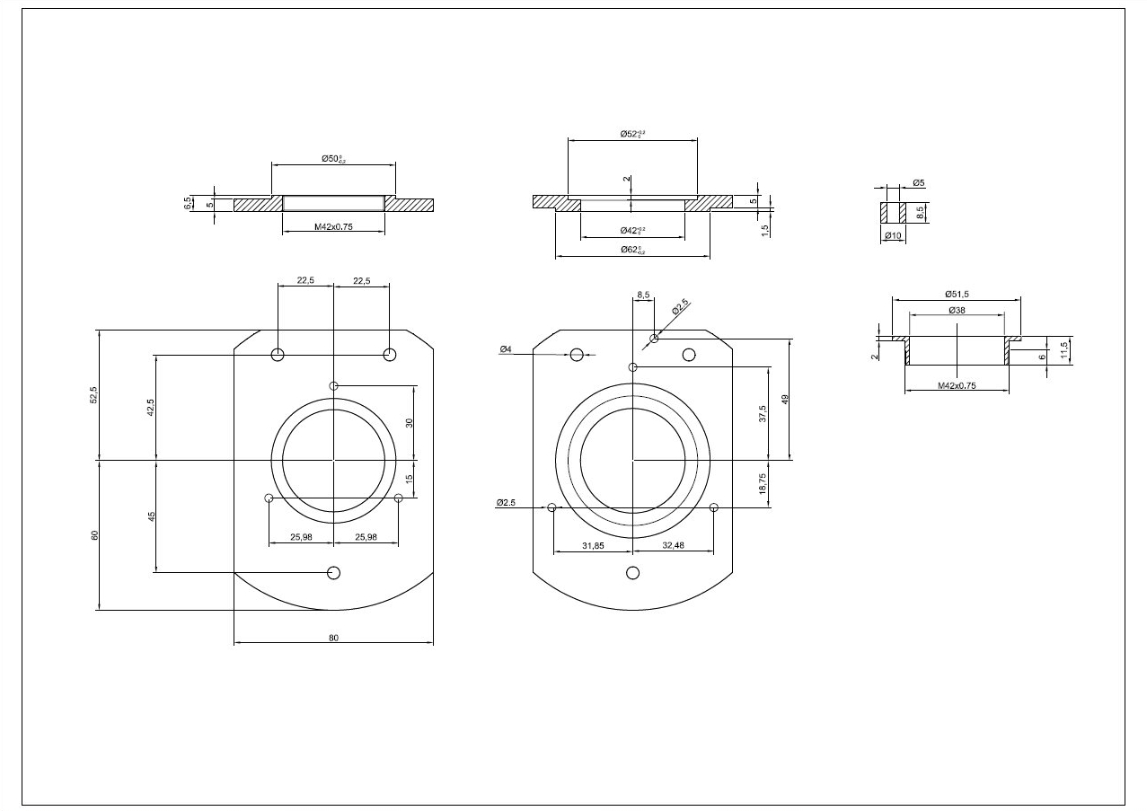
The core of the filter wheel, the one that connects wheel to camera and scope, has been realized in aluminum.
Top part is the lower body, the side close to the CCD camera. On the right there is the fixing collar with the standard T2 thread (M42x0,75). After I’ve positioned the lower body on the camera and tightened with the collar, I’ve marked the position of the two holes to have the wheel perpendicular to the camera body. This is not a requirement, the filter wheel will work in any position, it’s just for aesthetics. The two screws keep also the collar in place when I remove the filter wheel.
The lower part is the side that goes towards the scope. Also this part uses a female T2 standard thread.
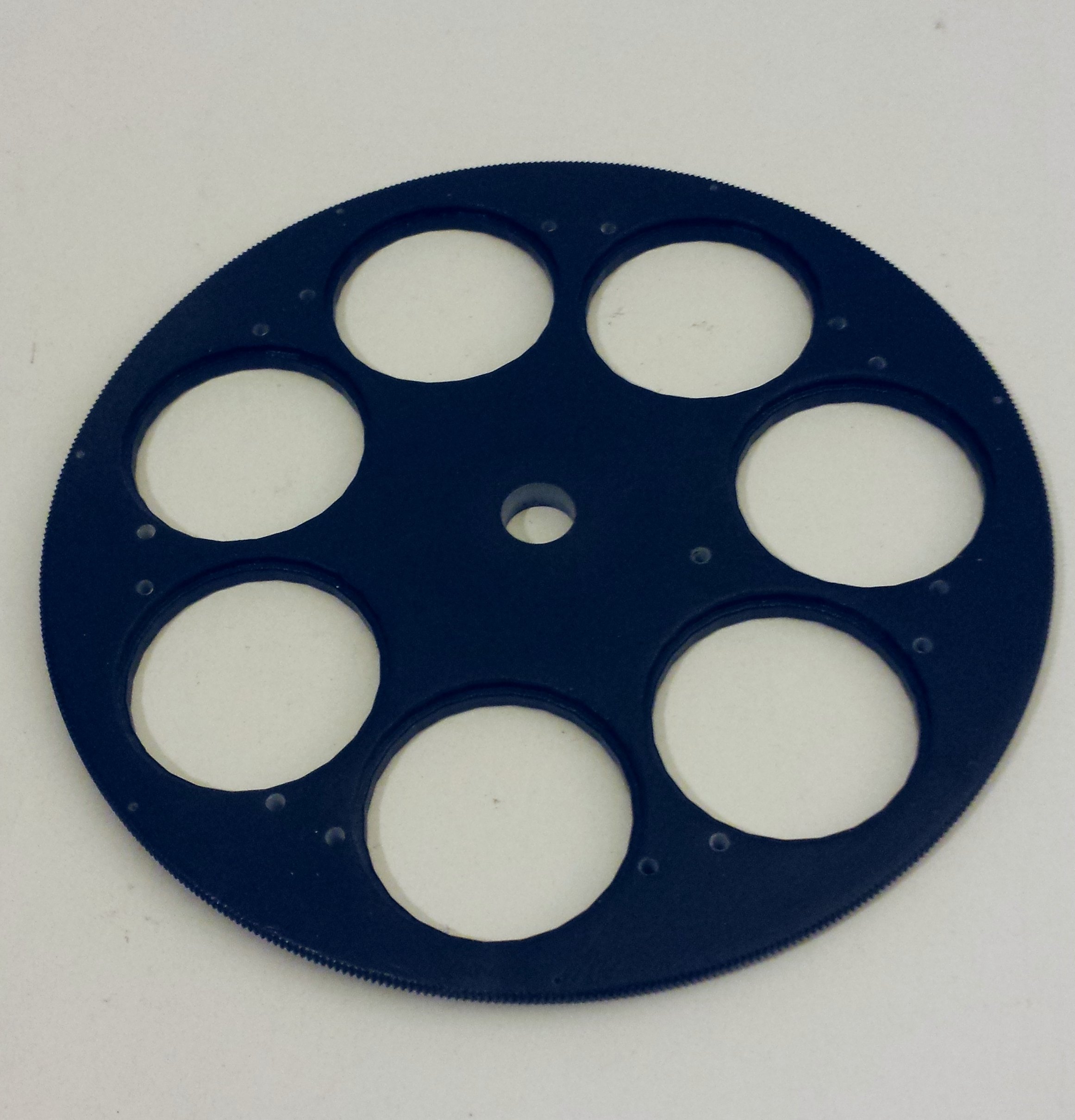
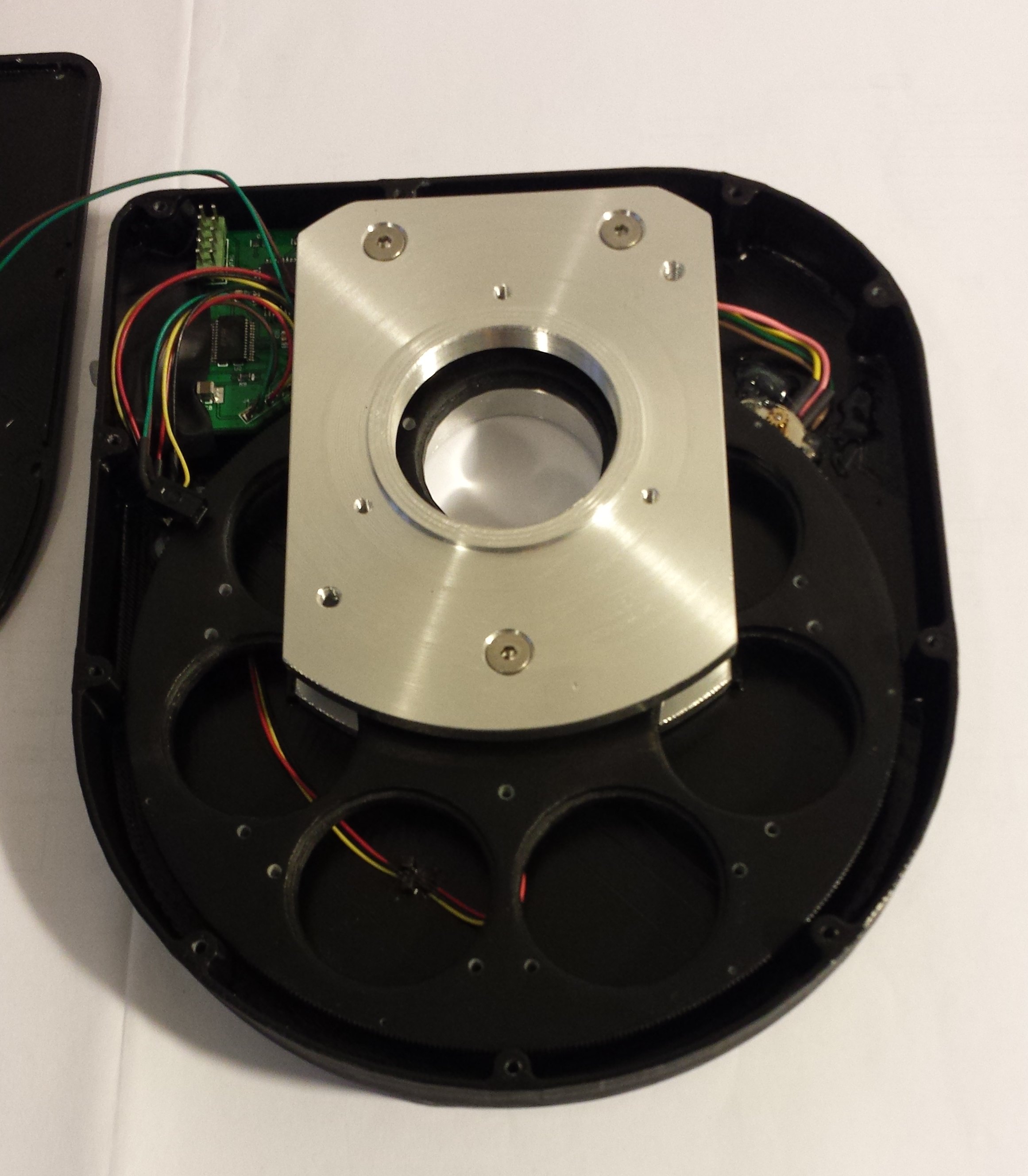
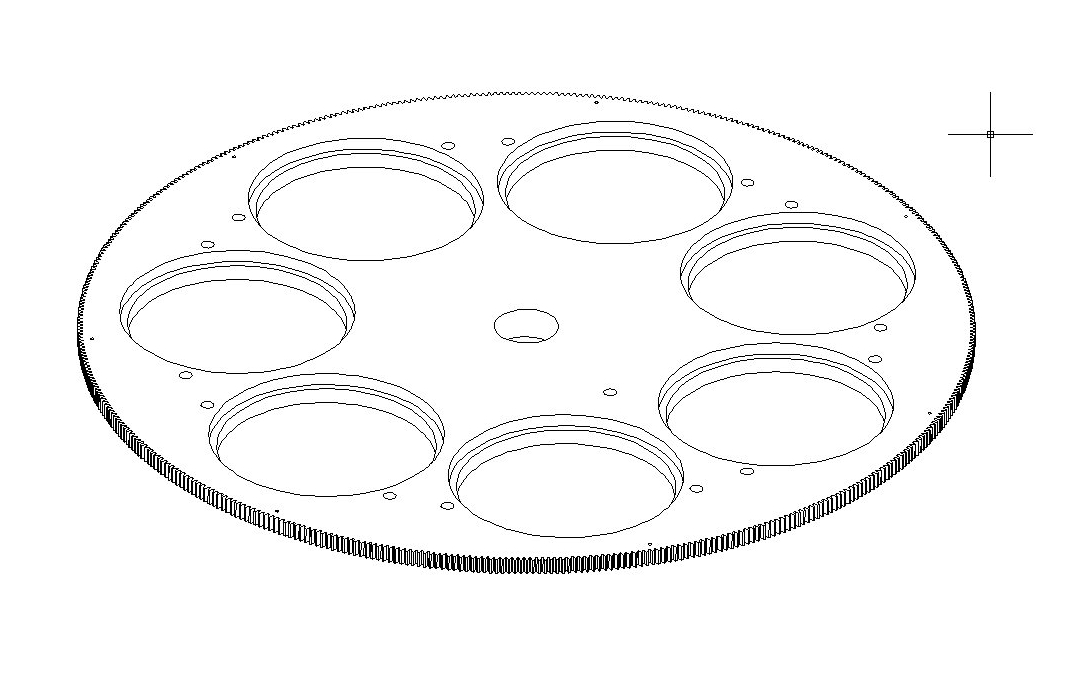
The wheel is the more complex part to realize. I decided to buy a set of 7 filters: L, R, G, B, Ha, Sii, Oiii unmounted and of size 36mm.
Given the outer diameter of the wheel, to achive an integer ratio with the stepper motor gear, the wheel must have 462 teeth!
The cost for machining it can easily exceed the cost of a complete commercial filter wheel, so the solution was to 3D print it with a high resolution printer. In this way I received the part almost ready to be installed: I just had to rework the holes for the slot positioning and the screws that hold the filters.
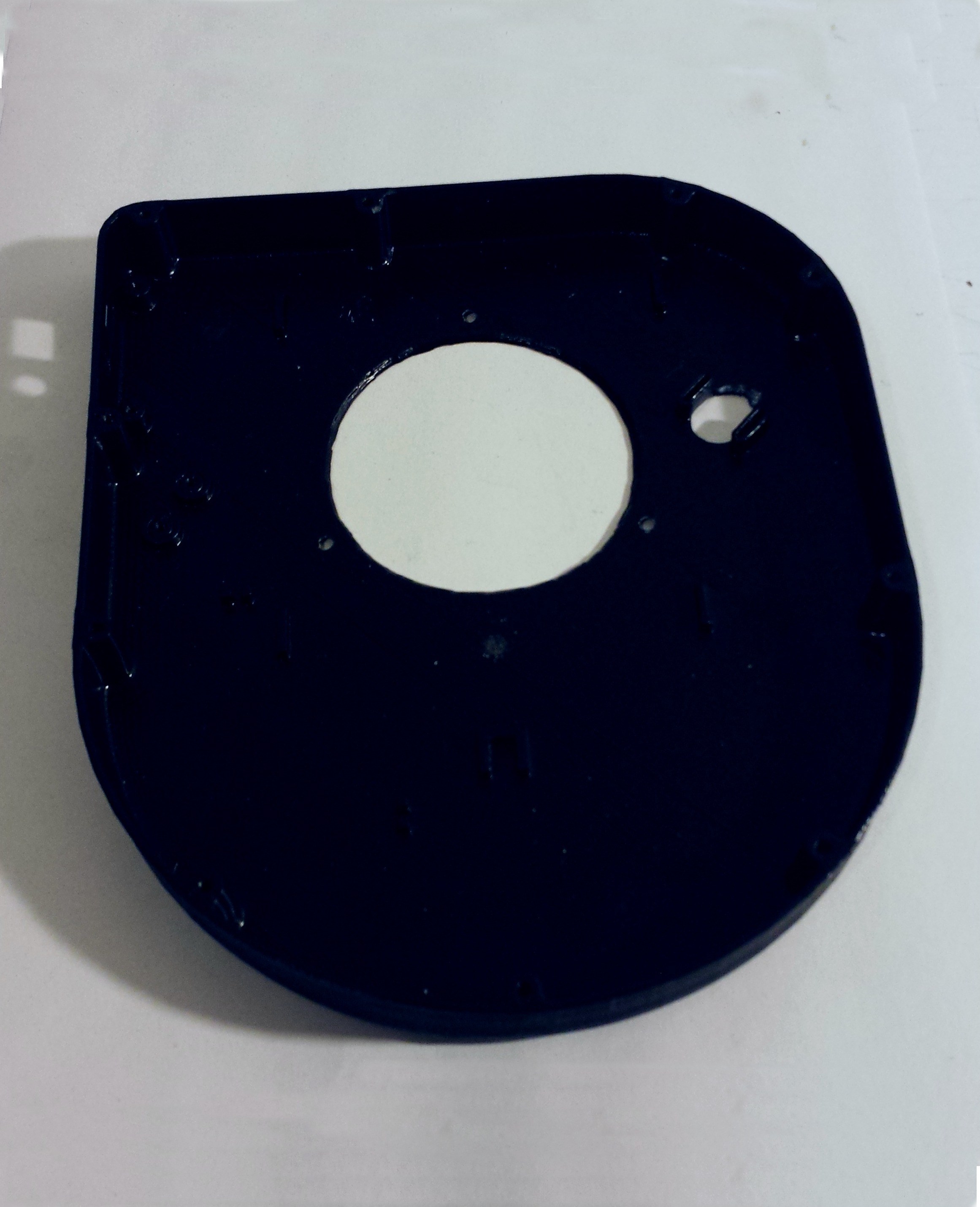
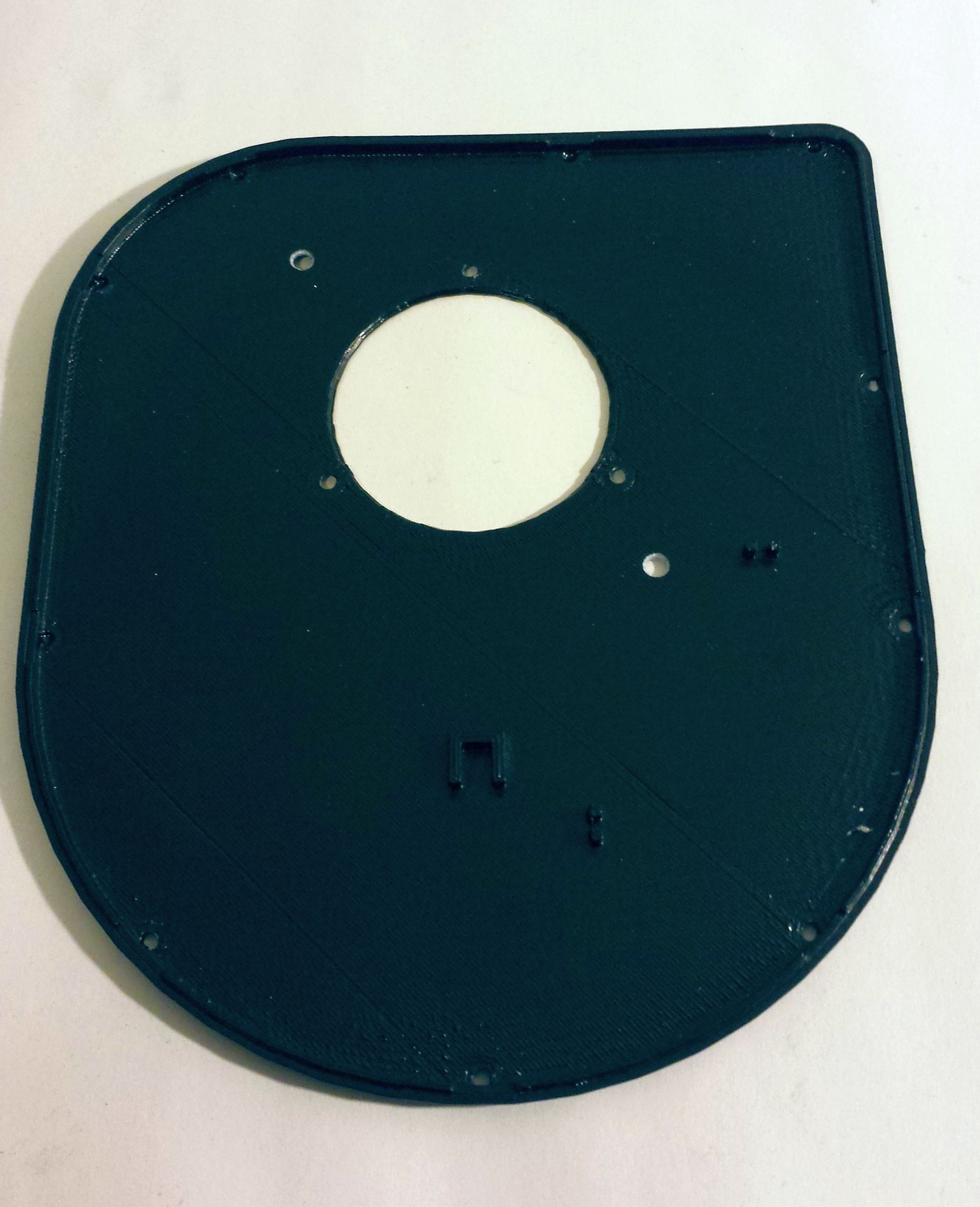
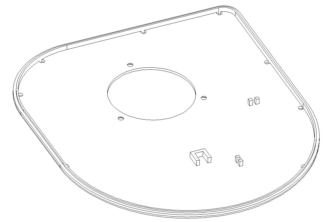
The enclosure has been realized with a lower resolution 3D printer and includes the supports for the stepper motor and the two optoswitches for home position and slot-in-place position.
 |  |
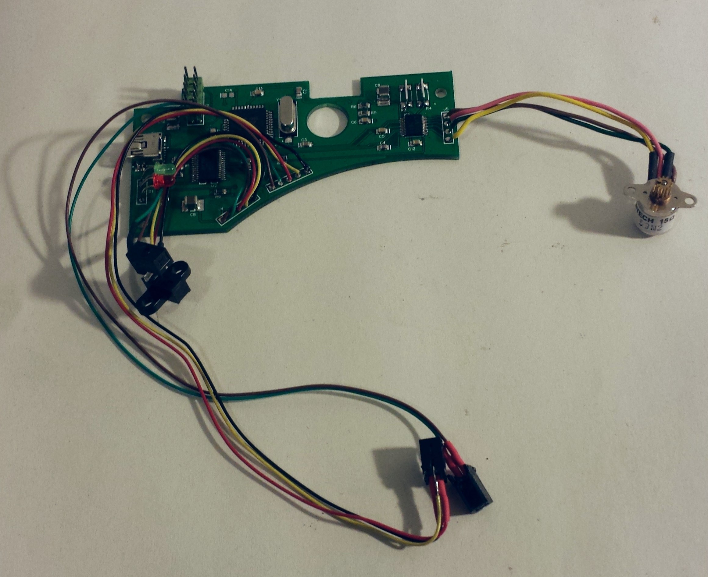
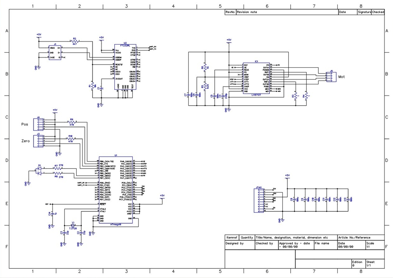
The PCB is the brain of the toy. Thanks to the very small power consumption, it can be supplied directly via the USB port without the need of extra power cables.
The controller uses an USB interface with unique chip identifier so, once connected a first time, it can be connected to every USB port without the annoying reinstallation of the drivers, thing that usually happens when you are hundreds miles from an internet connection 🙂
Via the device property interface the ASCOM driver allows to select the number of slots and store the configuration.
The movements from a filter to another is optimized to choose the shortest path, to minimize the filter change time. The accuracy of the positioning is granted by counting the number of steps of the motor and by an optoswitch with a very narrow light beam window. Since the cameras are really sensitive in the IR frequency, the optoswitches are supplied only during the movement of the wheel. When in place, the optoswitches are switched off and the wheel is hold in place by the stepper motor.
Here the device assembled.
And closed.
The 3D models of the body and the wheel.
Click on the pictures to open at full size.
 |  |  |
Schematic circuit.
Click on the picture to open the pdf file.
Mechanics: the upper and lower parts, 3 spacers Ø10mm h8,5mm and the collar.
Click on the picture to open the pdf file.
Although I’ve realized one fully functional device, the project is still under development.
Soon I’ll update the firmware, the ASCOM driver and some mechanical improvements.


