
Polar scope alignment on NEQ6
The best polar alignment is a minimum requirement for astrophotography. In a permanent observatory this can be easily achieved with several methods, but for those imagers who move to dark sites, you have to rely on your polar scope precision.
As my NEQ6 arrived I performed some ‘quality checks’ and I immediately noticed that the reticle wasn’t ok.
The first step was trying to align it aiming at far object, and despite the uncomfortable procedure I got quite good results.
A second attempt with the support of a webcam improved the precision, but since the small circle where you should put the Polaris is not aligned with the central cross (at least in my mount), I had problems in defining the ‘home’ position, either it is at 3, 6, 9 or 12 o’clock.
Why not using the webcam and some math to find the best centering of the reticle?
Said that, I developed a small application to show the video from the webcam, click few points and get a good centering of the reticle and ‘home’ position.
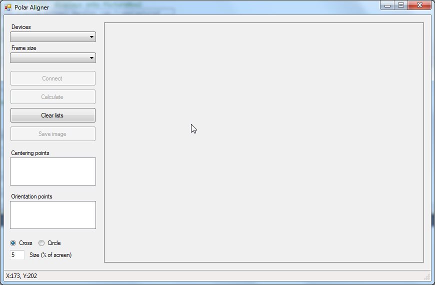
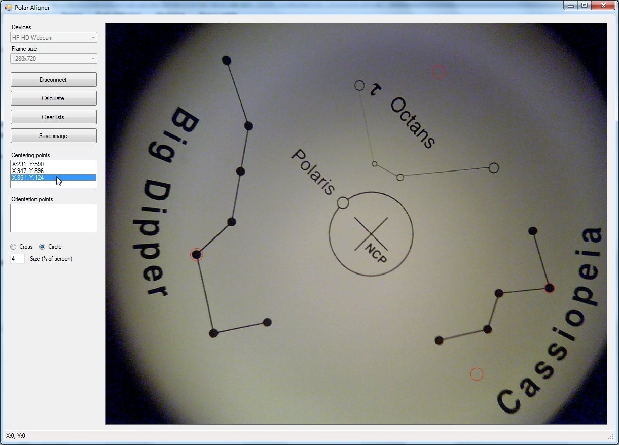
| PolarAligner Download the installer from the link at the end of this page, install and run it. This is how the window looks like. |
|||
click on the images for full resolution
|
|||
|
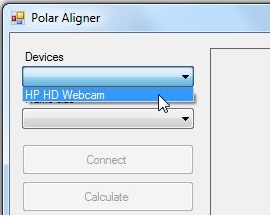
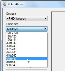
First select your webcam from Devices list. As you select one device, the Frame size list will be populated with possible resolutions for that webcam. |
|||
 |
 |
 |
|
|
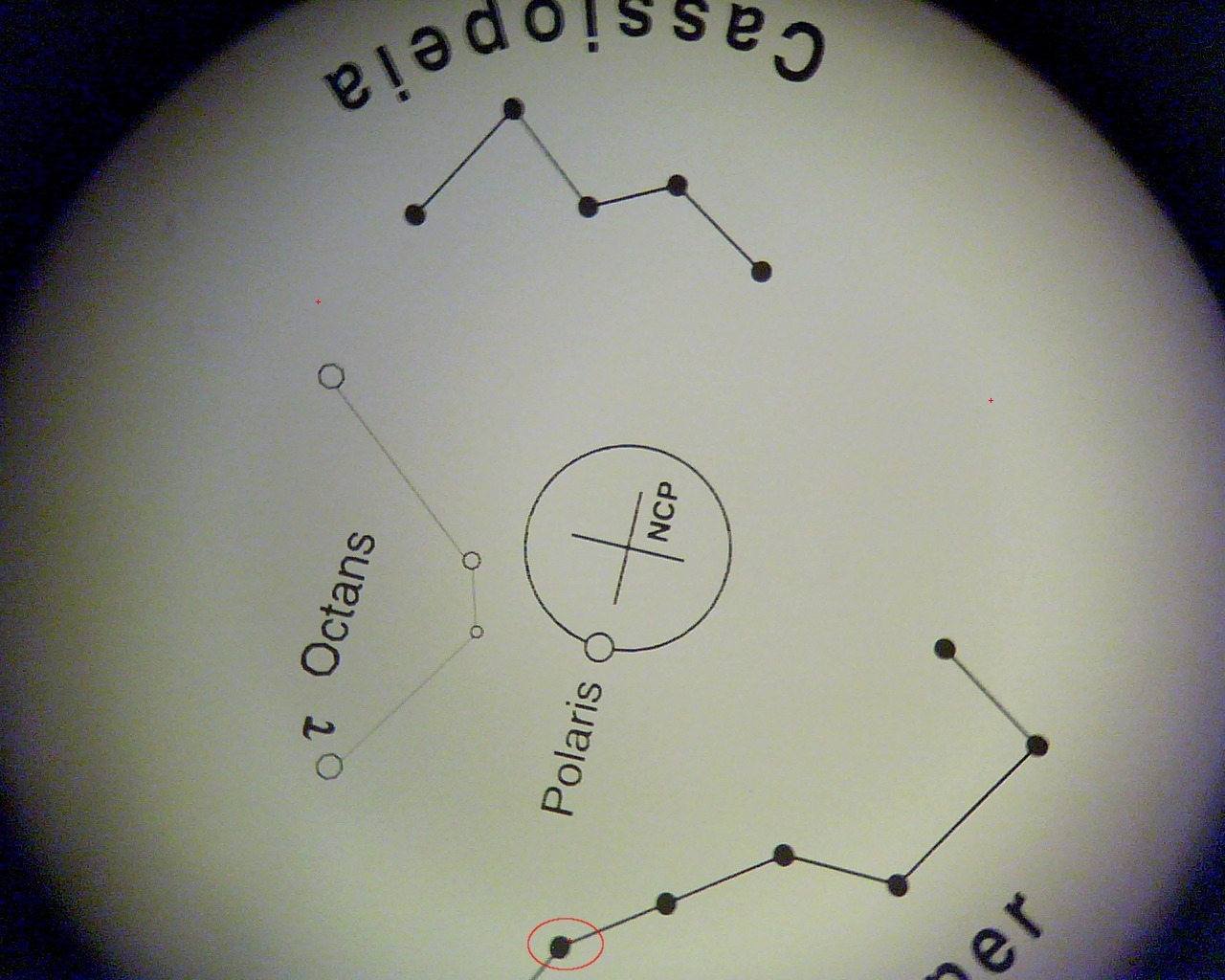
With the webcam well focused and placed in front of the polar scope, you should see the reticle on the screen. Next step is to find the rotational center of the RA axis. I found useful to align the RA circle at 24 o’clock and rotate the RA by 8 hours. Pick one point on the screen and a small cross (or circle, depending on your marker selection with the Radio Buttons) will be drawn. |
|||
 |
 |
 |
|
|
Don’t worry if you don’t pick the point exactly where it should be. Click on the point coordinates in Centering points list and use the arrows to move it where it should be. When you are happy of point position, just hit ESC key to release the point from ‘move mode’. |
|||
 |
|||
|
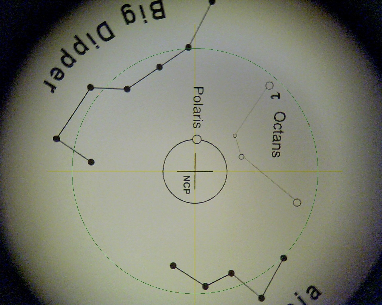
As you have placed the three points click on Calculate button. On the screen will appear a circle passing through the points and a cross that shows the rotation center. |
|||
 |
|||
|
If your reticle is not centered (as mine) you’ll see that the yellow cross do not match with the reticle cross. Align it using the grub screws. |
|||
 |
|||
|
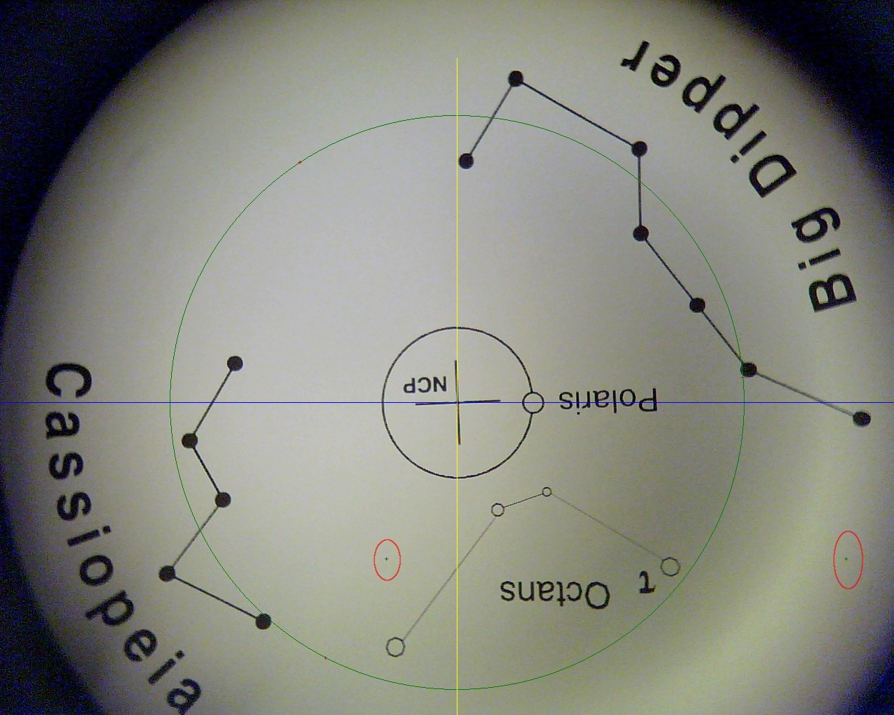
I usually align the mount to Polaris with the EQASCOM Polar scope alignment tool (project page, under documentation), so I need to know the ‘home’ position of my reticle. |
|||
 |
|||
|
A comparison of the ‘home’ position that I got aiming at a far building edge (long mark) and the new ‘home’ position found. Alignment errors calculated by EQASCOM are now smaller and also the autoguide graph shows less corrections. |
|||
 |
|||
|
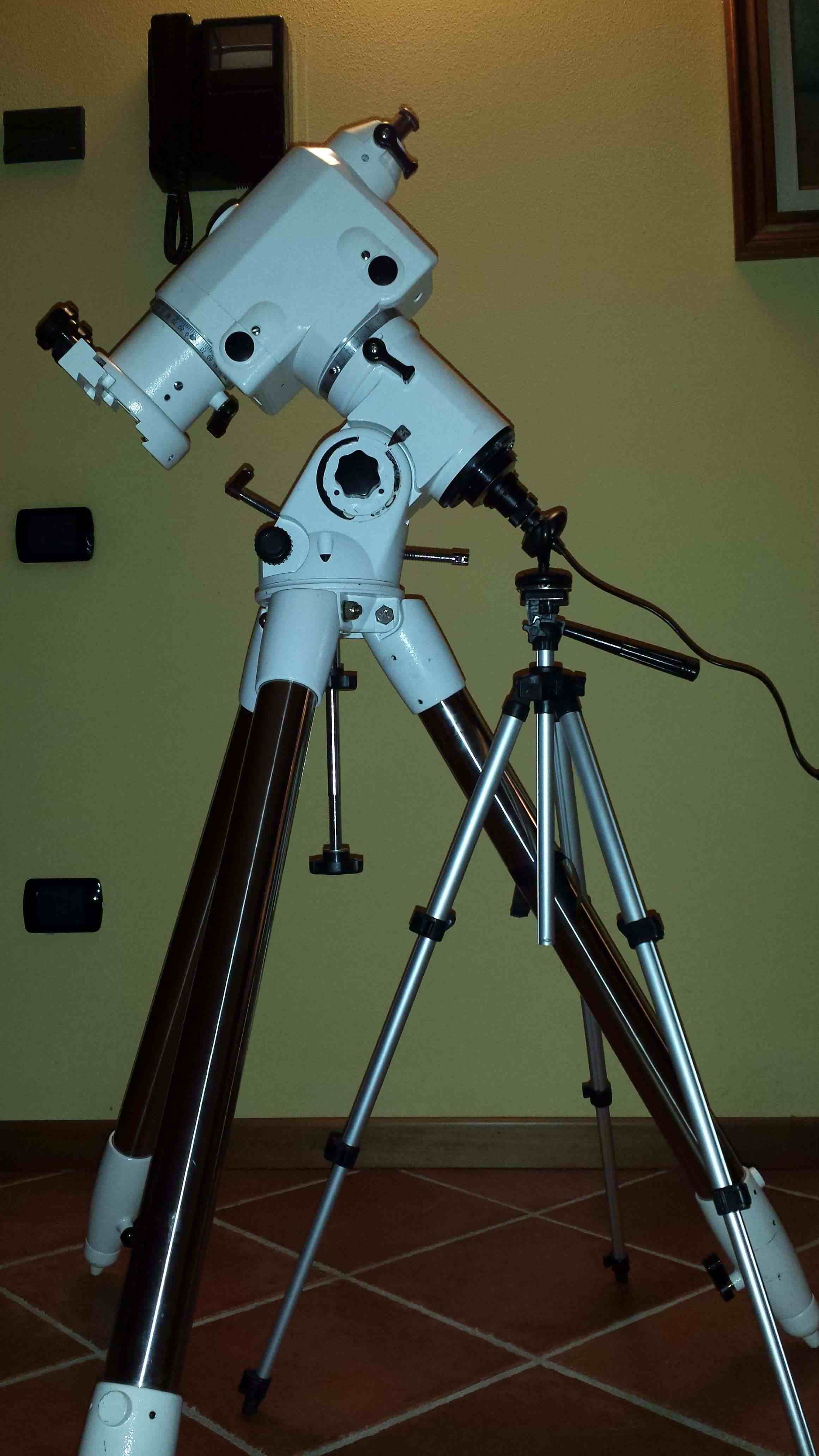
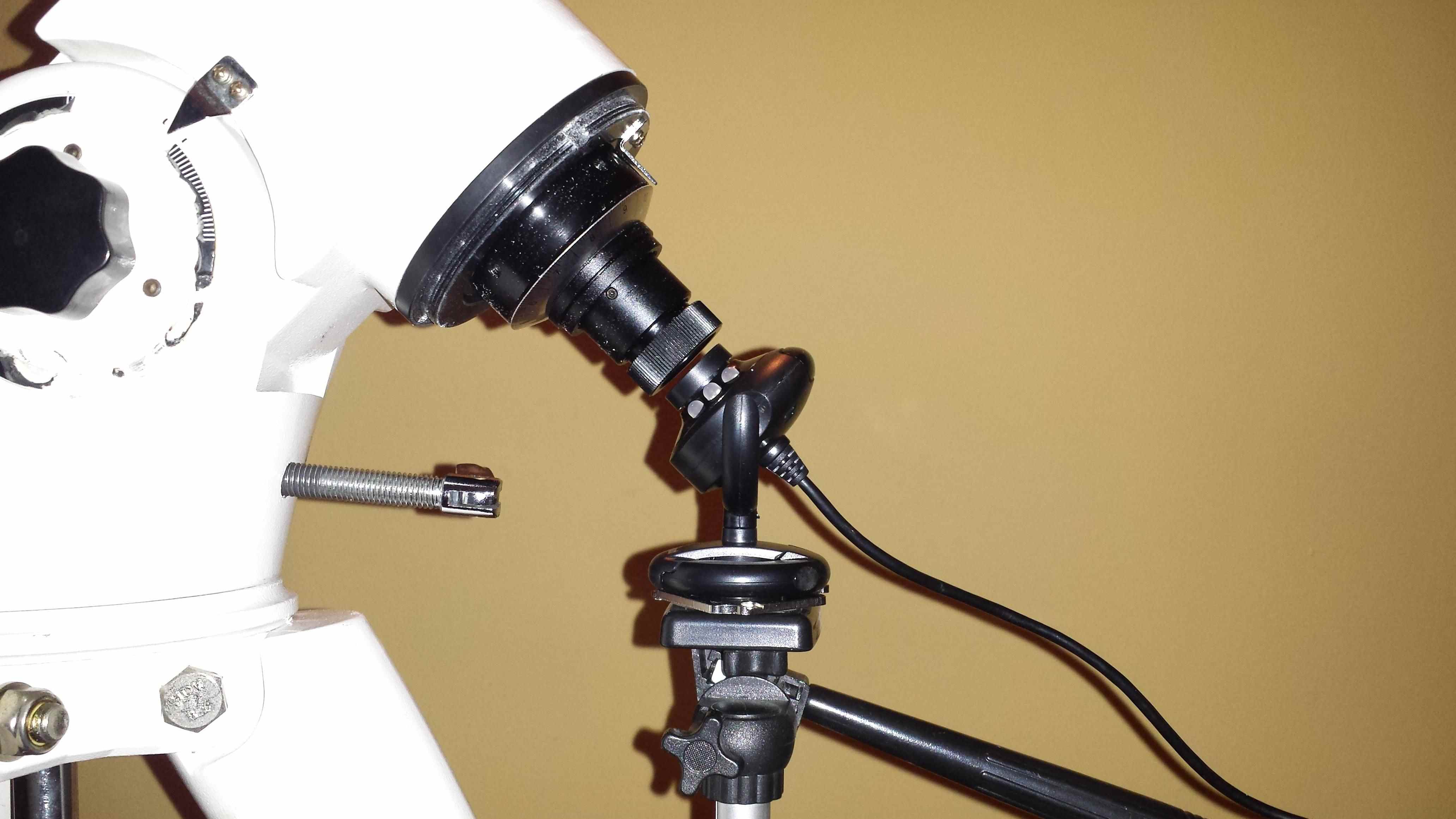
Here two pictures of the setup I used. Honestly, at the end I glued a couple of magnets under the webcam and I used a small ‘L’ shaped metal bracket to hold it so all the pictures are rotated by 90°. The mount up direction is on the right of all previous images. |
|||
 |
 |
||
|
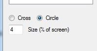
As mentioned before, in the interface there are also two option buttons named ‘Cross‘ and ‘Circle‘, and a text box where you can set the Size of the point markers, expressed in percent of the image height. |
|||
 |
|||
Here you can download the installer:
|