|
NEQ6 modding How to solve Latitude screw problem 1 – The wedge
|
|
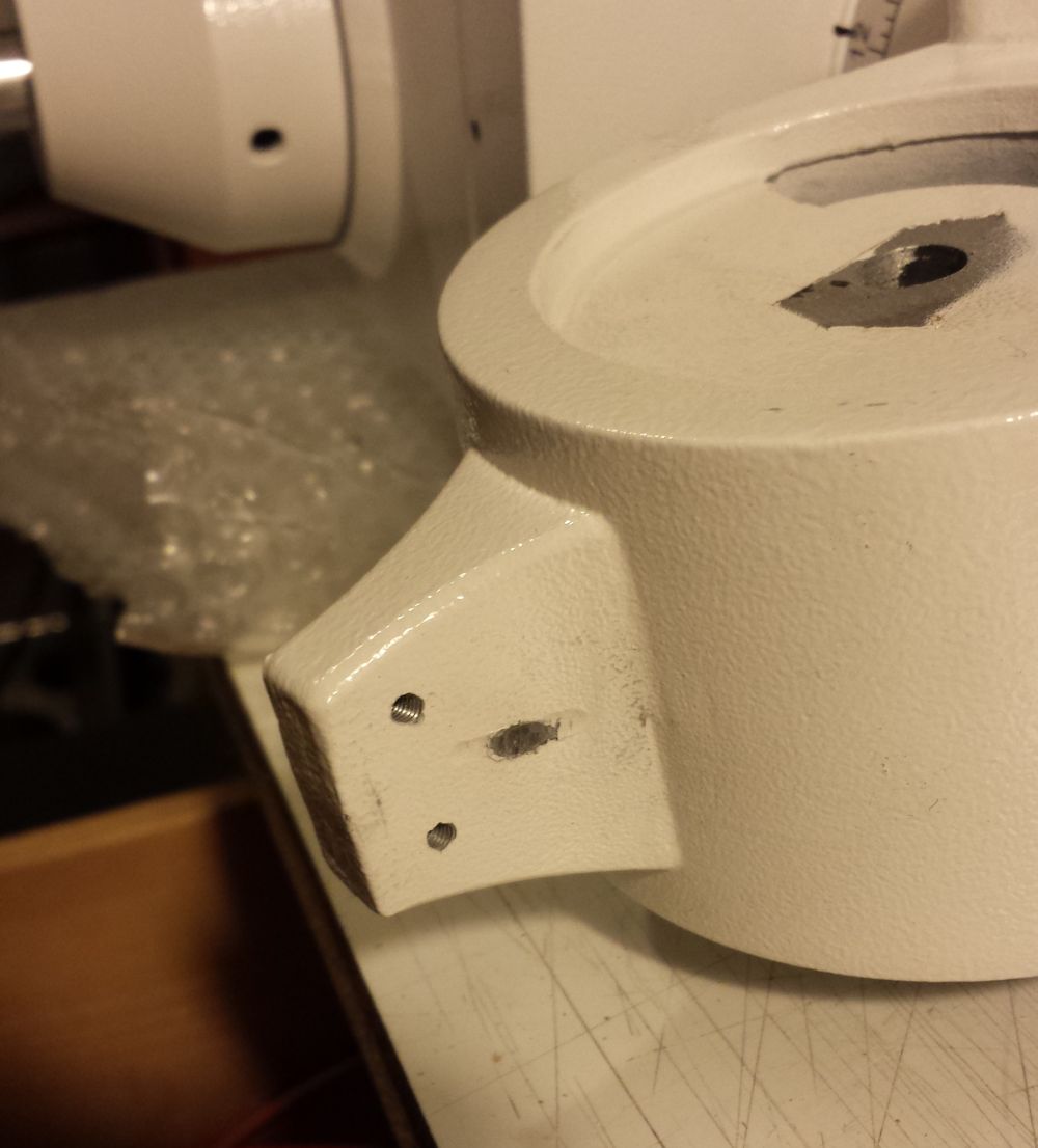
| Here the head already disassembled. Unfortunately, to reach the pin I had to break the black plastic caps (one with the scale and one with the brand). On my mount they were glued very well. Once you have access to the screw you need to loosen the three grub screws and then release nut and bolt which is the axis on which the whole head tilts. |
 |
|
|
|
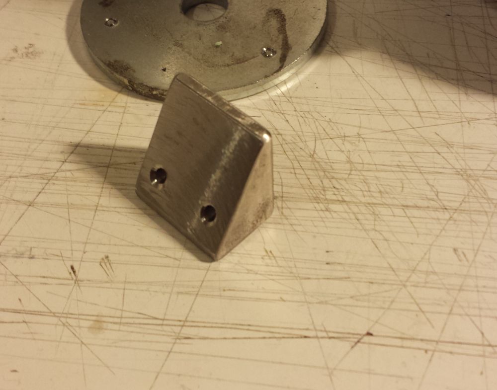
| Here the part to make. Since I’ve access to a friend’s workshop I milled a piece of stainless steel, but the part can be made of a material less hard (brass or bronze) just with a hacksaw and a hand drill. |
|
|
|
|
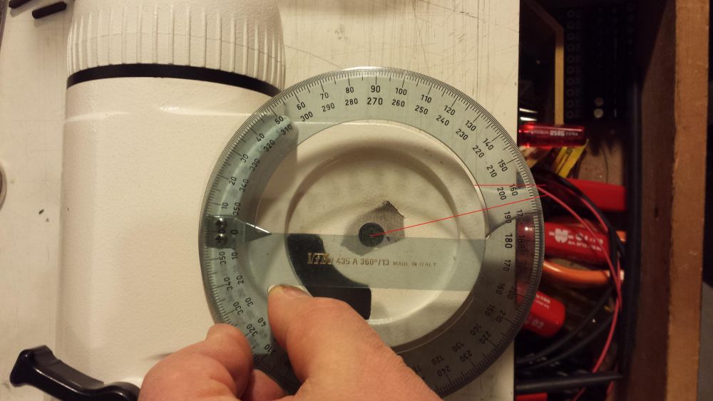
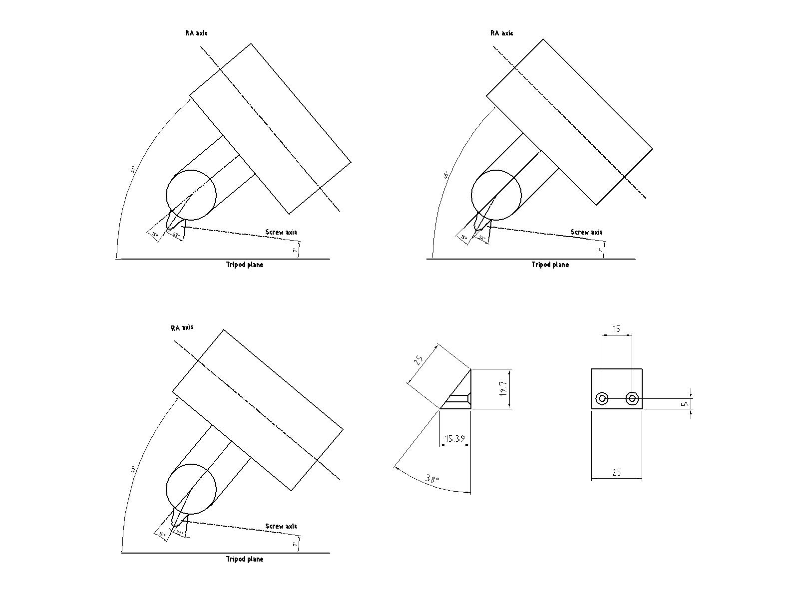
| Now some measure and calculation to get the right angle of the piece to be machined: the alt screw pushes on a part rotated by 75° but actually the surface on which our part will be placed is orthogonal to RA axis.
|
|
|
|
|
| The screw isn’t parallel to ground but tilted around 7°. |  |
|
|
|
Resuming some geometry it comes out that the angle of the wedge is equal to observer latitude minus 7° due to screw orientation. Below three cases for 40, 50 and my mean latitude of 45°.
|
|
|
|
|
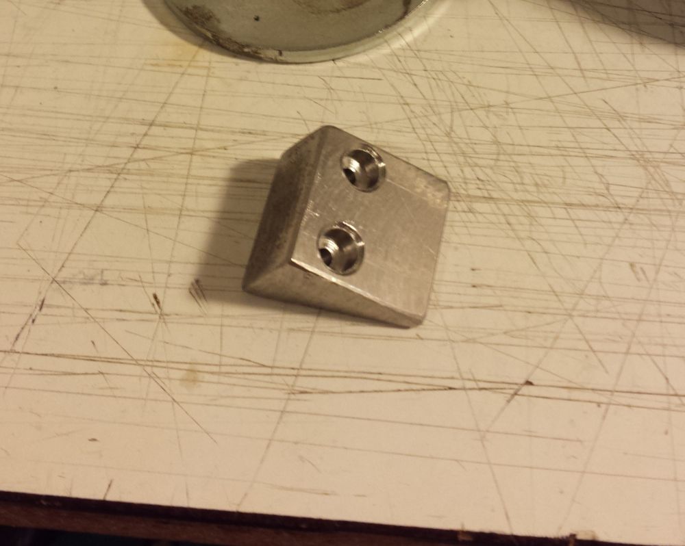
| Then, using the holes in the wedge as guide for the drill bit, you need to drill and tap the head. I’ve used stainless steel M3 conical head screws. |
 |
|
|
|
| Tighten the screws. | 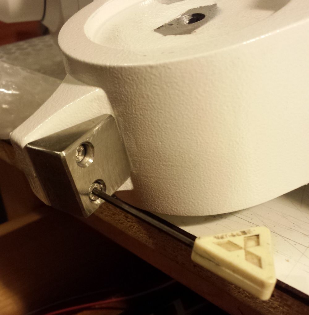 |
|
|
|
| The part in place. |  |
|
|
|
| The new angle of pressure of the screw almost near to 90° (despite the roughly placement of parts on the bench). | 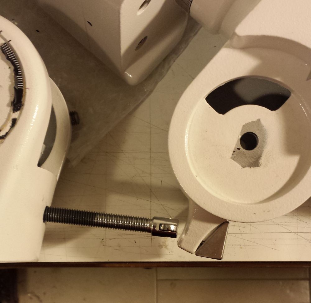 |
|
|
|
|
2 – The pin
|
|
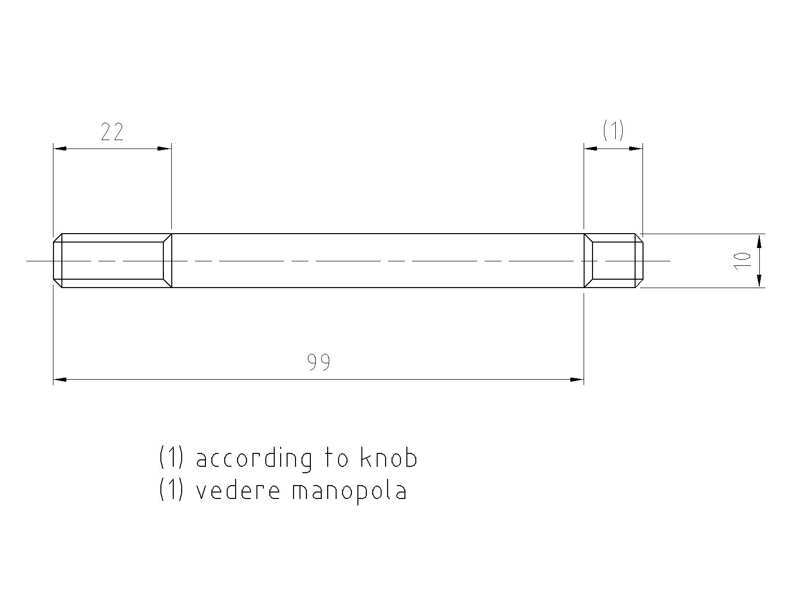
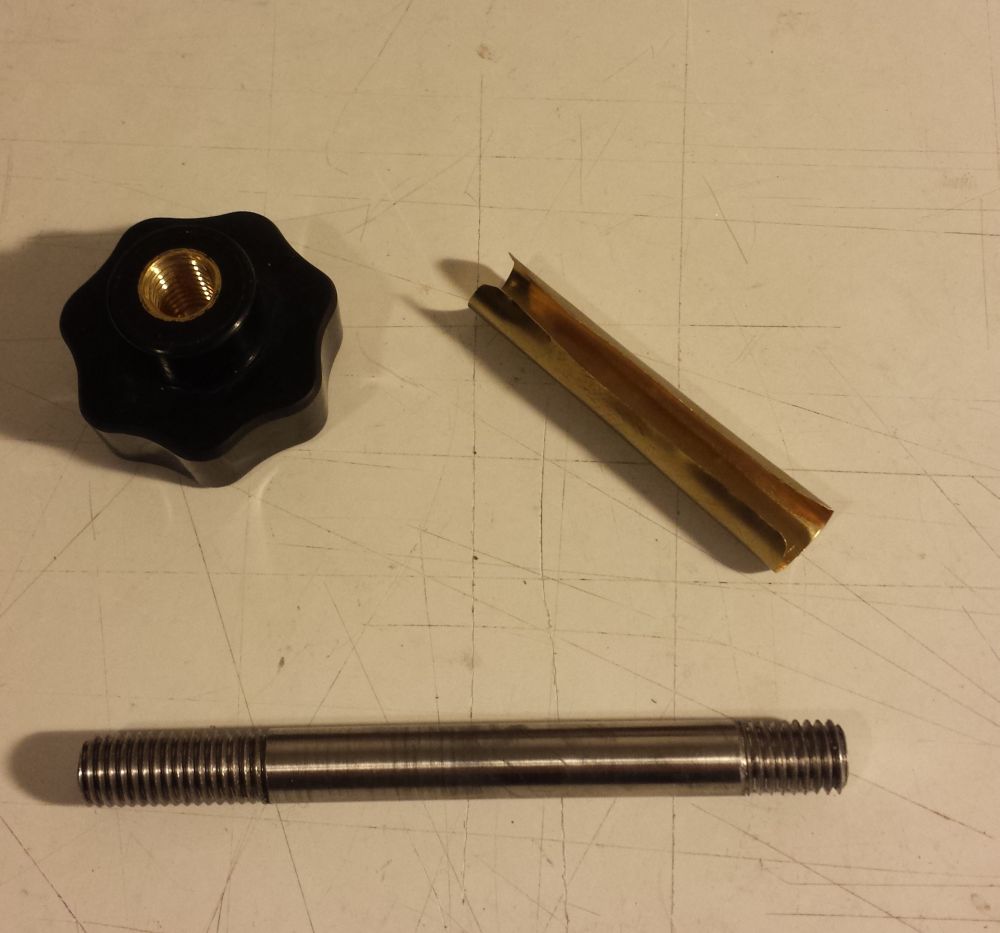
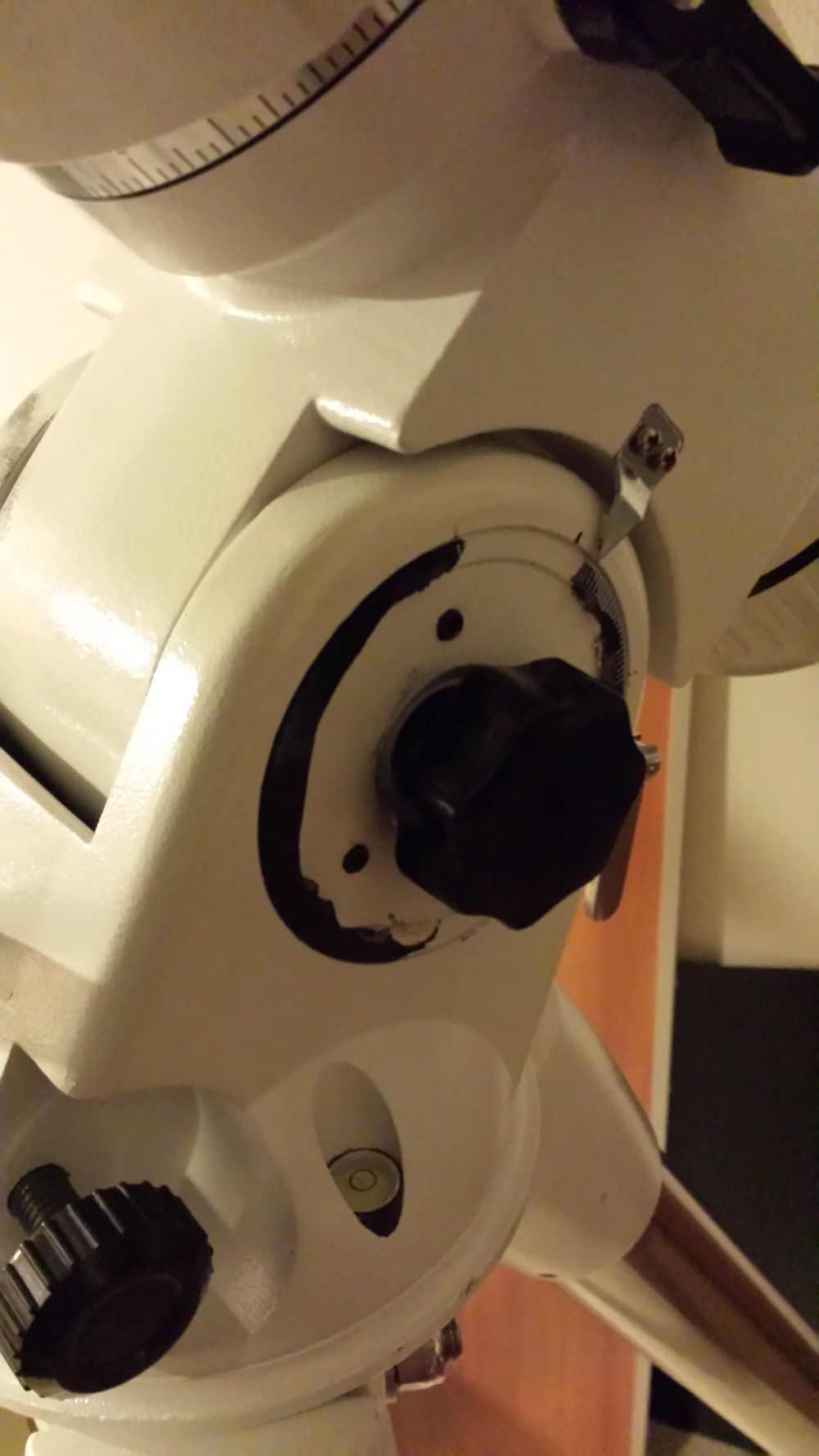
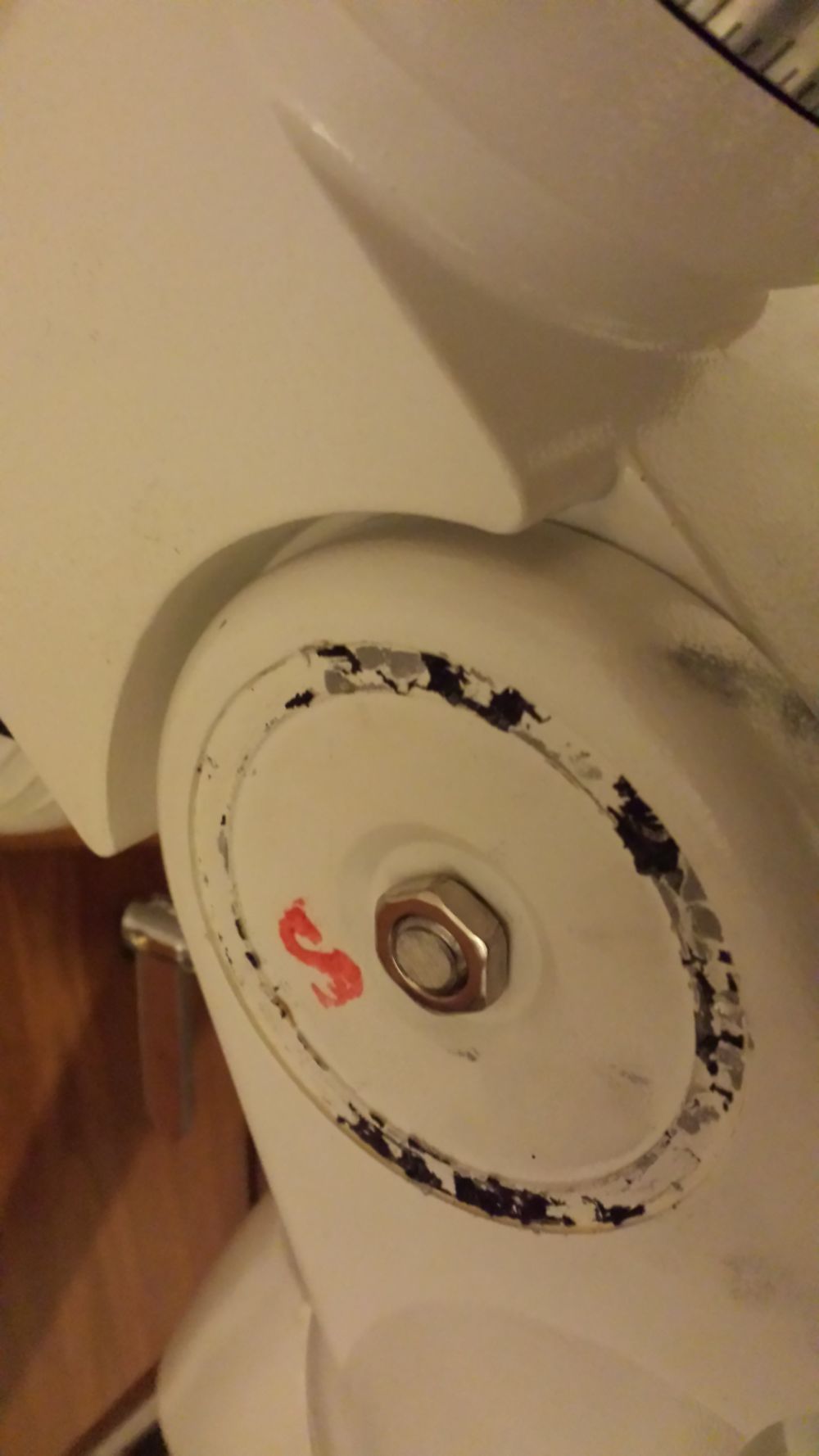
| The locking system of the latitude consists of the three grub screws removed before, pushing the big metal washer on the body of the mount. With the temperature span from summer to winter the friction may vary from smooth to very hard without any chance of tuning. Still using a stainless steel bar, I made a new 10mm pin threaded on both sides, locked it with the original nut on the side opposite the scale and then I installed a plastic knob (with female metal thread) on the other side. Unfortunately the manufacturer used a 10mm machined pin but then drilled the parts with a 10,5mm drill bit in order to compensate tolerances/misalignments. To avoid reworking parts and pin to 12mm I used a 0.2mm thick brass sheet (the one used to make custom RF shields) and cut a rectangle that I wrap around the pin before reassembling it. This ensured a better coupling of the parts. Tightening the three grub screws as enough as being able to move the head, and locking the head with the knob as you get the polar alignment will grant a stable setup in any condition. Manufacturing this part requires a lathe, but even a commercial M10 threaded bar may work well. In such case the brass sheet is mandatory to avoid the threaded bar wearing out the contact surfaces. |
|
 |
 |
 |
 |
| I’ve tested the modding with the following setup: Newton 8” f/4, guide scope 70 f/7, EOS 600D, guide cam AlCCD5 , 2 counterweights 5Kg plus one 1,5Kg With more or less 25Kg on the mount the movement was absolutely smooth compared to before.Hoping this may help, clear skies, Jeff. |
|