
JSFok main features
- ASCOM interface
- Temperature tracking
- Home position switch
- Up to 4 custom presets
- Full, half, quarter and heigth microstepping
- Settable run and hold motor currents
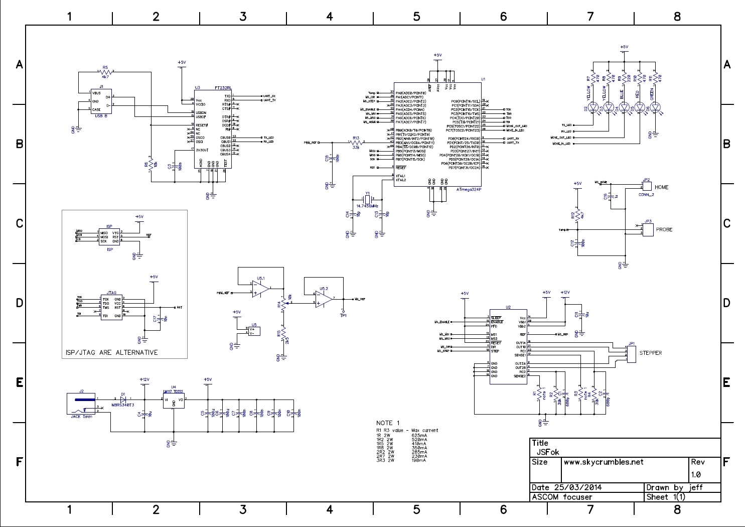
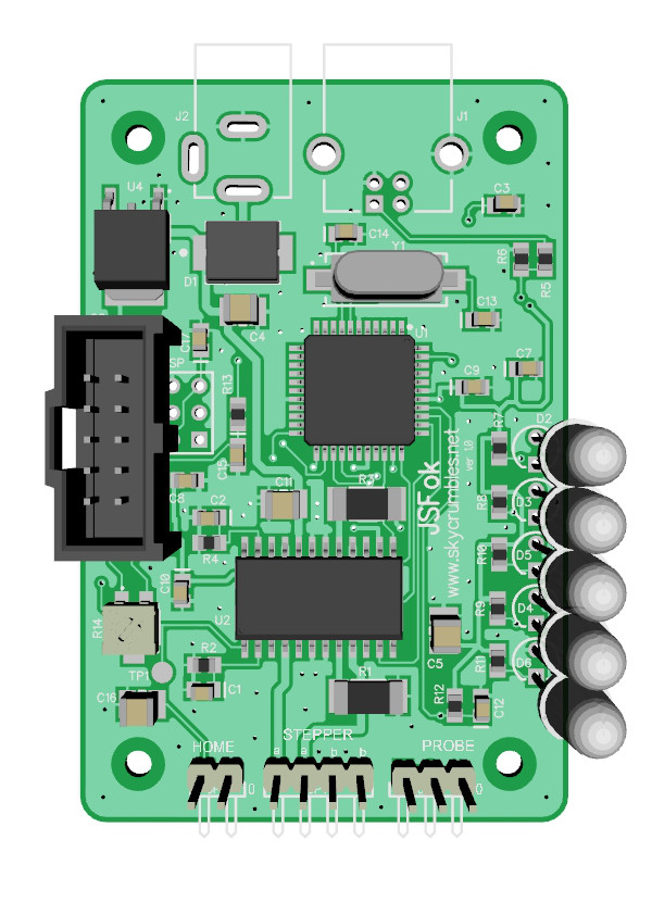
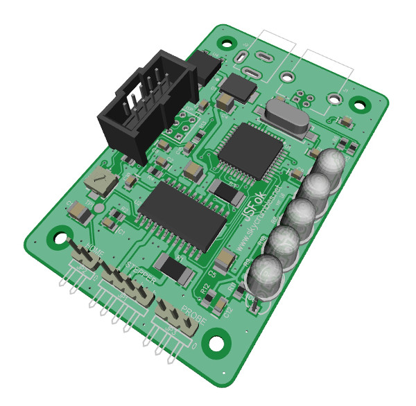
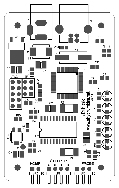
- Building the PCB
The size of the PCB is 46x70mm, dimensioned to fit the Teko box WK-2 (link).
If you don’t need to connect the device to more than a setup you can solder the wires directly to the pads of JP1, JP2 and JP3, otherwise choose a pluggable connector. I’ve used KK connectors from Molex.
IT’S MANDATORY THAT YOU DO NOT DISCONNECT THE MOTOR WHILE IT’S POWERED
The chip A3967 is protected agains short circuit, overcurrent, overheating but if you disconnect it live, you will destroy it.
The regulation of the motor current depends on the value of resistors R1, R3 and the value of Vref supplied by microcontroller according to the formula:
I = Vref / (8 * R)
Solving in function of R we get:
R = Vref / (8 * I)
In this circuit Vref is used to regulate the motor current and can vary from 1 to 5V (min to max), so use 5V to set 100% current.
Don’t worry if you think to use similar (but not exactly the same) steppers. In the ASCOM control panel we’ll be able to decrease full and hold currents, if required.
Since we have to choose between commercial values of the resistor, choose the near lower value. Fine tuning will be done with trimmer R14 or via ASCOM.
Example: for a motor current of 300mA, R should be 2.08 Ohm. Let’s choose the commercial value of 2 Ohm.
Then calculate Vref. From the first formula we get
Vref = 8 * R * I = 4.8V
With a voltmeter measure the voltage between TP1 and GND.
To be able to measure and regulate the voltage you could give a ‘long’ movement command via SW, or activate the ‘Hold when in position’ function and set 99 in the ‘Hold current percentage’ field.
Turn the trimmer until you measure Vref = 4.8V
Not all the motors can stand the nominal current for long time. They overheat soon, so don’t leave the motore at full current for too much time.
- Programming the firmware
Once you have soldered all components, the next step is programming the firmware. The device is based on an ATmega324 from Atmel, which can be programmed with several tool, some of them free e.g. PonyProg.
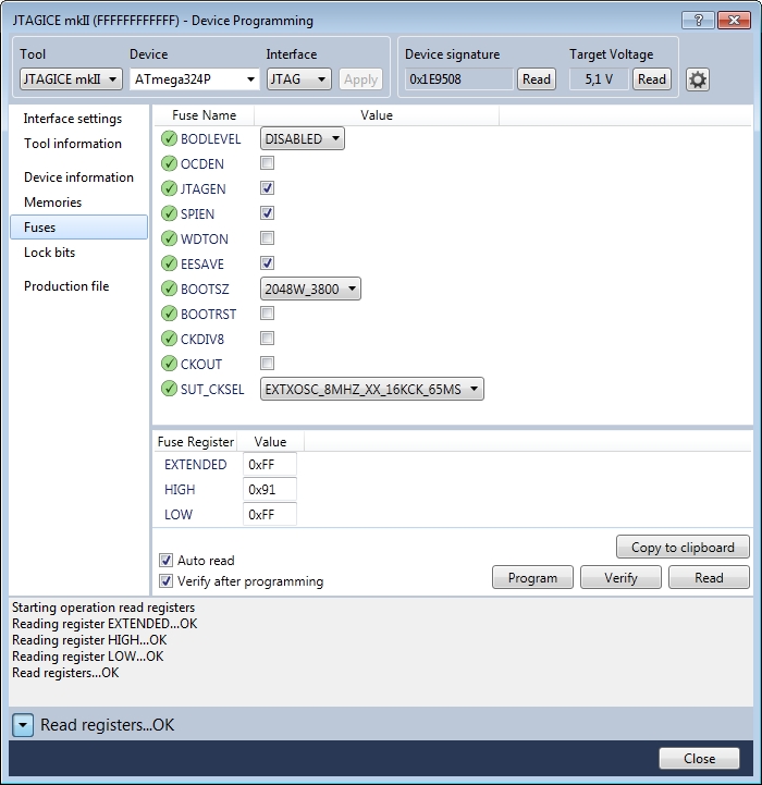
The ATmega324P comes with system clock sets as “8MHz internal RC” prescaled by 8 so effective system clock is 1MHz. First you need to change fuse settings to HIGH = 0x91, LOW = 0xFF and EXTENDED = 0xFF to switch to the external crystal.
Here a screenshot of how to program the fuses using AVRJTAGmkII and JTAG interface
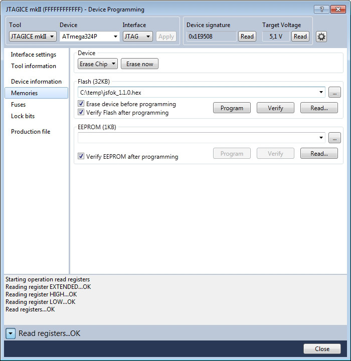
Now go ahead and upload the firmware. Select Memories on the left. In Flash section, browse to the file jsfok_1.0.hex and then click Program
That’s all on device side. Now let’s move to PC side.
- Drivers
The focuser uses a FT232RL from FTDI as USB 2.0 interface, which requires its specific driver to work properly. You can download latest D2XX drivers for your OS directly from FTDI homepage.
First install the FTDI drivers.
Connect the 12Vdc power supply to the device, then connect the USB cable to the PC and wait for the peripheral to be recognised.
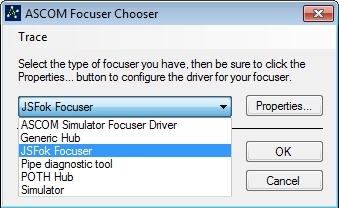
Once finished you need to install ASCOM drivers and if everything worked well, you’d be able to see the JSFok Focuser in the ASCOM chooser dropdown list.
Since that kind of USB chip is quite common in DIY projects, I’ve decided to use the unique serial number written into the chip itself to be sure to connect the the right device.
To do this should be better to have only the focuser connected because, as you try to connect the device, the driver enumerates all USB peripherals end goes thru them until the focuser is found.
Once found, the serial number of the USB chip is stored for the following connections.
Select the device and then configure it:
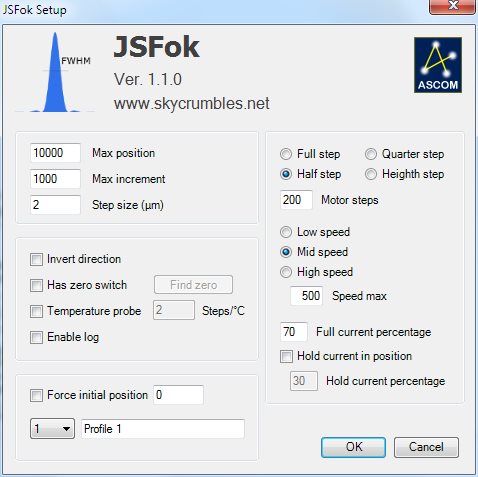
The interface is quite simple but let’s go anyway through all points:
Max position is the highest number of steps that the focuser can move to. Set a value a little bit smaller than the machanical limit, to prevent hitting it.
Max increment is the max ‘jump’ the focuser can do in a single movement.
Step size (µm) is the size of the movement the focuser does while moving by one single step. It can be easily calculated moving the focuser by a reasonably distance, measuring it and dividing by the number of steps. If the movement is e.g. 24mm over 10000 steps then set step size to 24/10000 = 2,4µm. This parameter is used by some SW during automatic focusing.
Direction inverted The movement is considered positive when the drawtube (or the focal plane) ‘exits’ from the focuser body. If you need to invert the direction, flag this option.
Has zero switch If your focuser has a ‘home switch’, the device has an input for a normally open contact (HOME). This feature is useful if your setup is in remote and you are not sure about the real position of the focuser (e.g. because of a connection fault or a power outage). Click on Search zero button and the focuser starts moving ‘in’ until it finds the home position (or a 20s timer elapses to prevent damages).
Has temperature probe Flag it if you have mounted the thermal probe.
Steps/°C its the number of steps for each °C of temperature variation. This parameter is quite critical and may lead to a bad focus tracking. A way to determine it is focusing at the beginning of the night and taking note of temperature and position, wait until the temperature drops by several degrees and refocus again. Dividing the difference of steps by the variation in temperature should return the parameter, which can be either positive or negative. BE SURE BEFORE ACTIVATING THIS FUNCTION!
Force initial position allows to change the value of current focuser position. As the device is connected, the last position value is loaded, but user can edit the field and set desired value (added in version 1.1.0).
Profile 1, 2, 3 or 4 selects a profile from memory. You can save up to 4 presets, so you can use one device on different telescopes (leaving motor, probe and switch on the OTA and building a single PCB). Every time you modify a profile and click OK, it is saved to PC for the next time. You can give a name for better understanding.
Enable log creates a file in ../Documents/ASCOM/ folder for debug.
Full, half, quarter and heighth step sets the microstepping level. Full step means that your motor makes a complete revolution moving by the amount of steps set in ‘Motor steps‘ field. Half means the you need double steps for a complete revolution, Quarter means four times and finally Heighth means eight times. When setting this parameter, consider all eventual gear ratios to avoid that the full movement of the focuser exceeds the limit of ‘Max position’ (65535).
Motor steps this is the number of steps of the motor (sometimes expressed in degrees/steps. divide 360 by this number to get steps/turn).
Low, Mid or High speed select the max speed of the motor. This setting affects also acceleration and deceleration.
Speed max set the max speed of the motor. Mid speed will be half of it and Low speed the quarter.
Full current percentage This parameter determines the motor current while moving. When setting this value, consider that stepper motors may stall and miss some steps if the current is too high when the load on the shaft is too low. Start with a 70% and increase if required.
Hold when in position If set, the motor is continuously powered also when in position, to prevent unwanted movement of the focuser. Some telescopes, like the SCs, don’t need this feature because there’s no chance for the mirror to move because of its weigth, but if you have a very heavy camera on a smooth focuser, it may move if you point at the zenith.
Hold current percentage most of the stepper motors cannot always work at nominal current or they overheats. This parameter determines the motor current after positioning. Set the lowest value you can set, until the motor keeps holding its position. Valid values are 25 to 99% but remember to set this value to have at least 1V as Vref on TP1. This is the minimum value accepted by the stepper driver A3967.
Connect to your SW and try to move.
Good… you have an ASCOM Focuser!!!
Here all the files you need:
| Version 1.1.0 | |
|
|
|
|
|
|
| Link to FTDI driver page to get the latest version of USB chip drivers | |
| Version 1.0.0 | |
|
|
|
| Click here for hi-res schematic |
 |
 |
 |
 |
 |
 |
 |
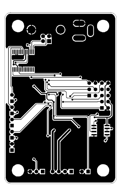 |
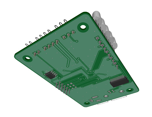
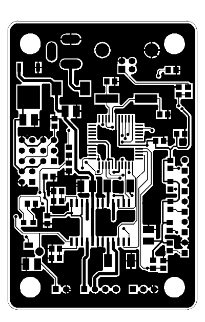
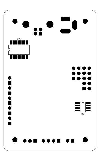
| Top silk | Top layer | Bottom silk | Bottom layer |
 |
 |
 |
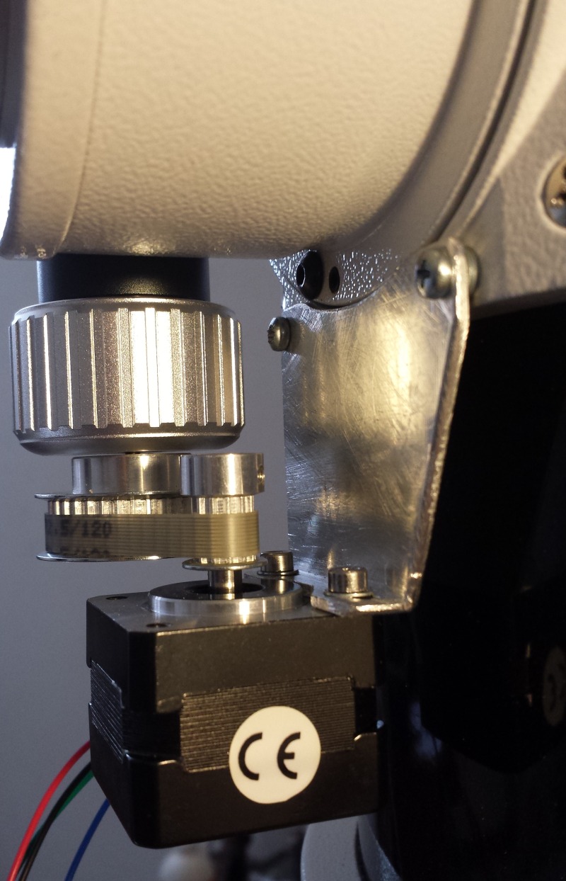 |
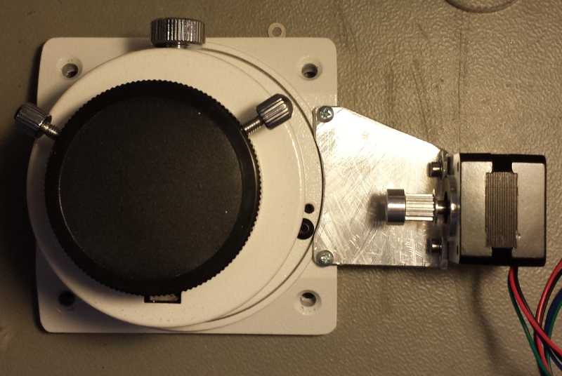
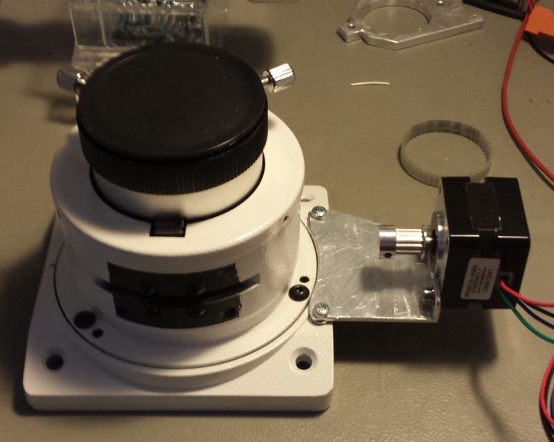
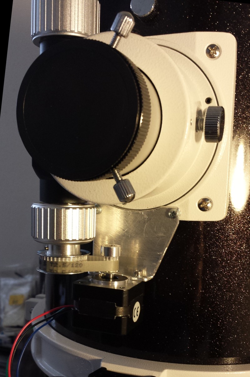
| In action |
| Some move command IN and OUT. On suggestion of a friend, the movement out is indicated by a red LED, while a movement in is indicated by a blu LED (red shift vs blue shift 🙂 ). |
| Temperature compensation |
| I’ve set a huge value in the field ‘Steps/°C’ to show the movement. Heating the probe with the fingers the focuser moves out. Then, as the probe goes back to ambient temperature, the focuser moves back to original position. |